Build Materials
Last modified: June 2020
CAD design of the MSL Quadrotor
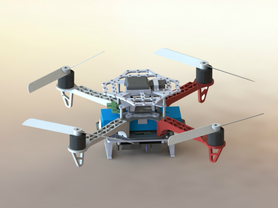
CAD Environment
- Solidworks 2016
- main assembly file: quadrotor.SLDASM
3D printing
- We used Ultimaker 2+
- For the sake of quality, consider slowing down the print speed, especially for large parts
- Use brim (at leat 5mm is recommended) in Cura to enhance adhesion to the print bed.
Bills of Materials
The following parts are required per quadrotor:
| Components | Qty | Link |
| PixFalcon Autopilot w/ GPS and Power Module | 1 | Amazon |
| F330 Frame | 1 | Amazon |
| Motors: Crazepony 4pcs Emax MT2213 935KV | 1 | Amazon |
| 8045 Propeller Set (2xCW, 2xCCW>) | 1 | Amazon |
| ESC: ZTW Spider 30A OPTO 2-6S LiPo 600HZ Simonk OneShot125 ESC | 4 | Amazon |
| Spektrum 9645 DSMX Remote Receiver | 1 | Amazon |
| Turnigy 3300mah 3s 30c LiPo Battery | 1 | HobbyKing |
| Spektrum DX6i 6 Channel Transmitter | 1 | Amazon |
| Pololu 5V, 5A Step-Down Voltage Regulator D24V50F5 | 1 | Pololu |
| Odroid XU4 | 1 | AmeriDroid |
| 64GB eMMC | 1 | HardKernel |
| Wifi Module for Odroid | 1 | AmeriDroid |
| RTC battery for Odroid | 1 | AmeriDroid |
| Male-Female Threaded Hex Standoff, 20mm Length, M2.5 Thread | 8 | McMaster |
| Female Threaded Hex Standoff, 10 mm Length, M3 Thread | 4 | McMaster |
| CP2102 Module USB 2.0 to TTL 6PIN | 1 | Amazon |
Assembly Guide
- Attach a MT2213 935KV motor to each F330 arm.
- Connect a ZTW Spider ESC to each motor. The ESCs should be physically attached to the arms with plastic tape so they do not interfere with propellers.
- Solder two 10 Gauge wires (red and black) to the bottom plate of F330, connecting the end of both wires to a XT 60 connector for battery connection.
- Solder two 16 Gauge wires (red and black) to the bottom plate of F330, on top of where the 10 Gauge wires are soldered. The other end of the wires are soldered to the input+/- terminals of the power distribution board for PixFalcon.
- Solder two 16 Gauge wires (red and black) to the bottom plate of F330, on top of where other wires are soldered. The other end of the wires go to the input terminals of the Polulu Voltage Regulator.
- Solder a DC power plug to the output terminals of the voltage regulator. This plug will power the Odroid.
- Attach the Pixfalcon power distribution board, Pololu voltage regulator, and the Odroid onto a laser-cut acrylic board. The Odroid is mounted with four 3D-printed Odroid Raiser (i.e. short standoffs) facing downwards. Attach the acrylic board to the F330 bottom plate.
- Attach two 3D-printed Landing Gears to the F330 bottom plate so the Odroid does not touch the ground directly.
- Sandwich the four F330 arms with the bottom and the top plate of the F330 frame, using four screws only. The other four halls are for the 20mm male-female standoffs.
- Attach a 3D-printed Pixfalcon Holder onto the top plate and tighten screws.
- Stick the Pixfalcon flight controller carefully onto the Pixfalcon Holder with a piece of glue sponge that is included in the flight controller kit.
- Put a 3D-printed Pixfalcon Cover onto the four standoffs so it covers the flight controller.
- Use another set of four 20mm male-female standoffs to sandwich the Pixfalcon Cover.
- Put a 3D-printed top layer on top of the four standoffs. Place the specturm receiver and the PixFalcon GPS module appropriately onto the top layer.
- Complete the wiring. Upload a PX4 Firmware of an appropriate version to the Pixfalcon onboard. Do not attach propellers to the quads until you make sure that the motors are controlled as intended.